Inspection of foam-cored sandwich with CFRP skins
For aerostructures it is crucial to inspect built-in sandwich structures for flaws. Thus, Dolphitech, reknowned provider of NDT products and services, made special foam core panels. They are bonded between two spread-tow carbon fiber reinforced polymer (CFRP) outer laminates and contain a range of embedded flaws at different depths. With the dolphicam2 and the newest Freya software version, these features were clearly detected and presented.
To benchmark the capabilities of the dolphicam2, a foam core panel bonded between two spread-tow carbon fiber outer laminates was made, containing a range of important flaw types. These features were embedded at different depths within the panel, where the ability to toggle between multiple C-scans with the dolphicam2 allows one to easily analyze different layers. This is a new capability with the Freya software version, which streamlines the analysis of multi-layered samples and enables one to inspect such parts more easily.
Test setup
The foam core is Rohacell 51 IG, which is a commercial grade, closed cell expanded polymethacrylimide (PMI) used for lightweight sandwich construction. The core is 0.23″ thick, the laminate on the inspection side is 0.18″, and on the back face is 0.08″. The embedded features include both flaws and manufacturing processes.
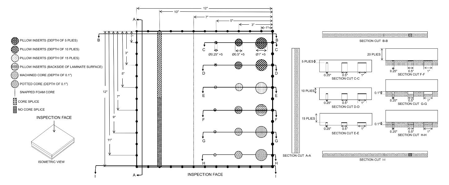
Technical drawing of the panel showing the internal features
Flaws are important to find as their presence can reduce the part strength and increase the likelihood of failure. Flaws are:
- pillow inserts to represent delamination,
- machined cores to represent skin-to-core disbonds,
- snapped foam core, which frequently occurs during manufacture, and
- “no core splice” (two core sections that have not been joined) to represent a region that has been missed when joining two core sections.
Manufacturing processes are important to inspect to ensure they are within dimensional tolerances and to have an accurate idea of their location. The manufacturing processes are:
- potted core regions formed by machining the foam core and then potting it, and
- a core splice formed by adhesively bonding core panels together, whereby multiple core panels may need to be “spliced” together for larger size layups.
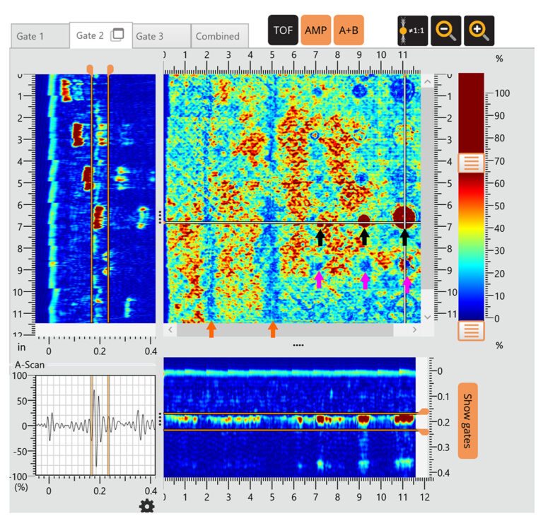
Amplitude view for Gate 2. The jet color palette has been used to highlight the variation
The panel was inspected using a dolphicam2 in pulse-echo mode and a TRM-AF-3.5MHz transducer module (TRM). The TRM has a central frequency of 3.5 MHz and an Aqualene delay line. It is an excellent all-rounder for composite inspection in aerospace with a good balance between penetration and resolution for this application. The sample was inspected from the “inspection face” where water was used as couplant. A velocity calibration was performed, where velocity was found to be 3041 m/s.
A stitched map of 12 × 12 tiles was acquired over the “inspection face” for the panel. Stitched maps are uniquely enabled by dolphicam2’s live C-scans. They are formed by freehand positioning the transducer and stitching the data from each location together.
Findings and conclusion
In short, the test series – or rather its results – were more than satisfactory. With the dolphicam2 platform, it is possible to detect a variety of features including simulated delaminations and skin-to-core disbonds, as well as a snapped foam core, a “no core splice”, a potted core, and a core splice.
This was all achieved with a standard pulse echo setup without the need for any through-transmission technique. Moreover, the Freya software version introduces the ability to quickly toggle between and view multiple C-scans, which streamlines the analysis of multi-layered samples and speeds up the overall inspection time.
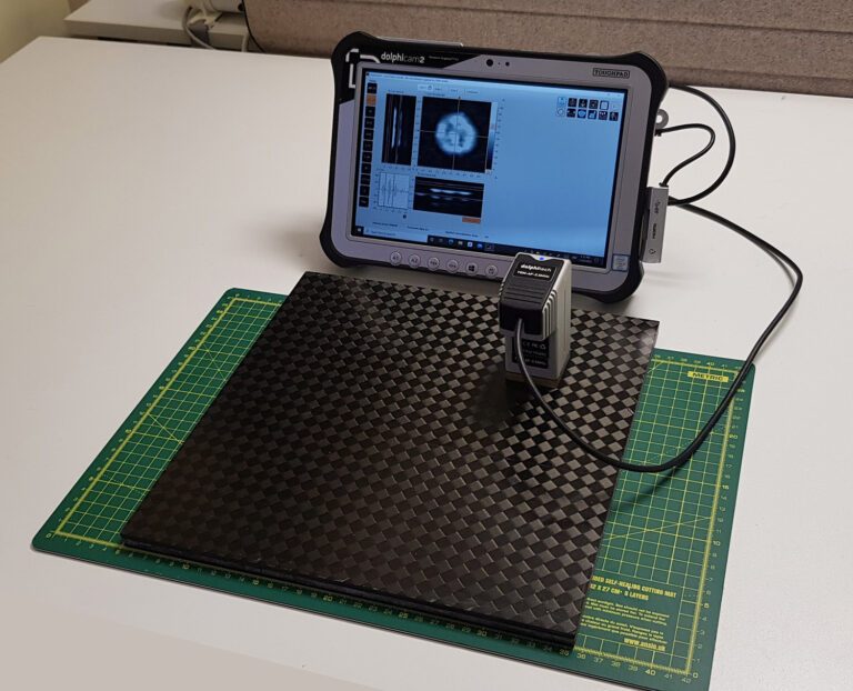
Setup using a dolphicam2+ and TRM-AF-3.5MHz transducer module on the panel
Contact:
Dolphitech Germany GmbH, Germering
Ludger Epping, Sales Manager DACH
+49 151 19 14 64 12
Ludger.Epping@dolphitech.com
www.dolphitech.com