FAQ
“Lightweight design” stands for lightweight design methods, and implies a design technique that aims to achieve maximum weight savings. Reasons for this include targeted cost or raw material savings, as well as increasing payloads or simplifying assembly and handling. The way in which lightweight design can be achieved also varies. For example, integrative design, material and manufacturing technology means can be used in an overall structure.
Reasons for a targeted lightweight design can be different. Often, a reduction in weight, especially in the automotive or aerospace sector, can reduce energy consumption and thus costs and raw materials in use. In the case of frequently accelerating or decelerating loads (e.g. road or rail vehicles, elevators, robot parts), payload can be increased and operating costs reduced. Lightweight construction continues to offer a flexible alternative for assemblies, or in building construction.
In general, materials with low density and high mechanical properties are used. This can be a monolithic material or a composite material. Metallic lightweight materials include aluminum, magnesium and titanium. In addition, fiber composites are nowadays considered a frequently used category of materials.
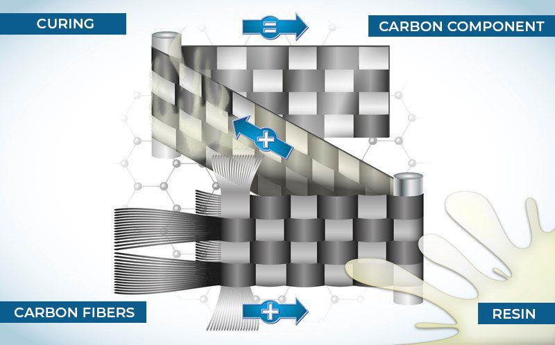
A composite is a material composed of several components, so that each of the individual components can be clearly distinguished physically from the others. The individual components then interact with each other in such a way that the new material has new, improved properties that could not have been achieved with any of the individual components alone.
A composite material consists of at least a matrix and a reinforcement. The matrix is the embedding material for the reinforcement. It serves to hold the reinforcement material together, protects the reinforcement from environmental influences, and is primarily responsible for the uniform application of force to the reinforcement. The matrix can be metal (MMC), plastic (PMC) or ceramic (CMC). Similarly, there are diverse reinforcement types. These are often categorized according to their shape. Thus, for example, a distinction is made between fiber-reinforced, particle-reinforced composites. The reinforcement serves to carry the load, and thus increases the mechanical properties of the matrix in the composite.
Fiber composites are fiber-reinforced plastics (FRPs) in which fibers are embedded in a plastic.
Plastics, also often referred to as plastics, are macromolecular chains of covalent bonds that are produced synthetically. Depending on the type of plastic, properties can vary widely from elastic to brittle, or transparent to completely opaque. Mechanical properties, heat resistance or chemical resistance depend strongly on the choice of macromolecules, manufacturing processes and the admixture of additives (admixtures). Plastics are divided into 3 categories: Thermoplastics, Thermosets, and Elastomers.
Plastics are divided into 3 categories: Thermoplastics, Thermosets, and Elastomers. Thermoplastics consist of linear or branched macromolecules and can be plastically deformed after heating, as well as melted at elevated temperatures.
In thermosets, on the other hand, the macromolecules are spatially closely cross-linked. As a result, thermosets cannot be plastically deformed or melted. Elastomers are often colloquially referred to as rubber. These consist of wide-meshed cross-linked macromolecules, which allow deformation under load, but retract elastically as soon as the load is removed. The cross-linking also makes it impossible to melt an elastomer.
Thermoplastics and thermosets in particular are frequently used in fiber composites. Their low density provides an optimal basis for lightweight construction. By adding reinforcing fibers, desired mechanical properties can be achieved.
Thermoplastics must be melted in order to be processed. The most commonly used melting processes in industry include extrusion and injection molding. Thermosets, on the other hand, are processed in the not-yet-crosslinked state. For pure (non-reinforced) components, the material is primarily molded.
A fiber is a material form in which the ratio between length and diameter is>10. Fibers are divided into continuous (length>50 mm), long (length =3-50 mm), or short (length<3 mm).
In principle, any fiber material can be embedded in a matrix. However, glass, carbon, aramid, nylon, basalt, and natural fibers are most commonly used in combination with a plastic matrix.
Unreinforced plastics have low mechanical properties compared to metals. These are generally sufficient for applications in packaging, electrical engineering, building services, etc., but are not suitable for heavily loaded structural components in mechanical or vehicle engineering. By embedding high-strength and stiff fibers into the plastic, a combination material is created, which has stress-strain properties between those of the individual components.
Carbon is the English word for carbon. Thus, carbon fiber is often referred to as carbon fiber.
A single carbon fiber has a diameter of about 7 µm. By way of comparison, a glass fiber has a diameter of 24 µm, and a human hair 50-70 µm.
The abbreviation CFRP stands for carbon-fiber-plastic composite.
Because the carbon fiber is black, it gives the composite its bold color, but it is often used as a “designer” look.
Carbon fiber is manufactured from organic starting materials in fiber form. For this purpose, materials are used that can be converted into an infusible intermediate (pretreatment, or oxidation) and then carbonized (carbonization) in a pyrolysis process to form carbon. Finally, an optional post-treatment (graphitization) can be carried out to increase the mechanical properties. Throughout the manufacturing process, the fibers remain stretched to force an orientation of the atomic structure in the fiber direction. This in turn promotes high strengths and gradients in the fiber direction. Process temperatures are increased from about 300 °C (oxidation) to 1500 °C (carbonization) and up to 2500 °C (graphitization). The structural diversity of the fibers can be achieved by means of the anisotropy of the graphitic layers, which can be controlled by the manufacturing parameters, and thus offers a wide range of properties.
Cellulose, PAN (polyacrylonitrile) or pitch are most commonly used as the starting fiber (precursor).
Carbon fibers are divided into
- HT – high strength (high tensity)
- IM – intermediate modulus
- HM – high stiffness (High Modulus)
- UM – (Ultra Modulus)
- UHM – (Ultra High Modulus)
- UMS – (Ultra Modulus Strength)
- HMS – High Stiffness / High Strength (High Modulus & Strength)
Typical properties of carbon fibers would be
Property | Typical HT fiber | Typical UMS fiber |
Density [g/cm3] | 1,8 | 1,8 |
Tensile strength [MPa] | 3500 | 4500 |
Tensile modulus [GPa] | 250 | 4,6 |
Elongation at break [%] | 1,5 | 1,1 |
Individual fibers (filaments) are bundled together to form yarns for further processing. The designation “K” implies that 1000 filaments are combined into one yarn. Thus, with 24 K fibers there are 24,000 filaments in one yarn, with 48 K there are 48,000.
CFRP components are influenced by several factors. Essentially, matrix and fiber properties play a major role, but fiber volume content (i.e. how many fibers are incorporated in the matrix) and fiber orientation also play a decisive role. Other influencing factors are the processing methods or processing parameters.
A unidirectional reinforcement (UD) is a reinforcement in which all fibers are present in one direction (orientation). In UD-CFK, the unique fiber properties are used bundled in one direction. This means that the composite has the highest strengths in the fiber direction, while there is no reinforcement of the matrix in the transverse direction.
Isotropy refers to the independence of a property from direction, i.e. that the property is the same in each direction. In an anisotropic material, the properties are direction dependent and thus vary from direction to direction.
A distinction is made between reinforcing fibers according to length between short, long or continuous fibers. In most cases, bundles, so-called rovings, are made up of thousands of individual fibers.
These are further processed into scrims, woven fabrics or braids. In the case of scrims, a distinction is made between continuous-fiber scrims, with defined directions of individual fiber bundles, and short-fiber nonwovens of arbitrary orientation.
Woven fabrics or scrims can also be dry or in the form of prepregs. In the case of prepregs, the fibers are already pre-impregnated with resins for further processing, so that no matrix system needs to be added during the manufacture of the component.
Short fibers consist of bundles of chopped fibers up to 3 mm in length. For some applications, they are reduced by milling, which produces lengths <1 mm and destroys the bundles. In this case, a finely divided fibrous filler is obtained, which is often added to thermoplastics to produce so-called “compounds”. These are further processed by injection molding, among other methods. Thermosets can also be filled with short fibers and molded into components as a pressable compound. It should be noted here that the reinforcing effect is relatively low.
Long fibers are processed into mats, among other things, where a thin polymer sizing, the so-called “binder”, helps to fix the fibers together. Since the fibers are oriented randomly in all directions of the mat plane, they are referred to as “random fiber mats”.
Continuous fibers are produced as rovings and wound onto spools so that they can be easily unwound for further processing. In direct manufacturing methods, rovings are infiltrated with liquid resin or thermoplastic melt and then formed directly into a component. For tubes, this is done by fiber winding, and for sheets by fiber or tape depositing. Other processes are via textile semi-finished products, which offer greater flexibility in component design.
Scrims consist of individual layers of parallel rovings. These can be stacked on top of each other with any orientation. Due to the unidirectional orientation of the individual layers, a scrim allows maximum fiber volume in the component, since there is no curvature of the rovings. This thus allows maximum component strength of components.
Woven fabrics are single layers of rovings crossing each other at right angles, called warp and weft. By crossing the rovings, they become curved woven fabrics allow easy processing of continuous fibers, especially for curved components.
A braid consists of regularly intertwined rovings with an oblique orientation to the component edge. This semi-finished product geometry allows increased shear strength of the components. Among other things, braids can be manufactured in component geometry, and are thus particularly suitable for tubes and three-dimensional structures.
Components made of CFRP are relatively expensive to manufacture compared with metal components. Therefore, they are mainly used where their advantages can be of great benefit. This is the case, for example, in the aerospace industry, in aircraft construction, and to some extent in automotive engineering. In addition to such structural applications, CFRPs offer advantages in sports equipment, such as bicycle frames, tennis rackets or fishing rods, due to their low density.
The following is a comparison of the typical properties of glass fiber and carbon fiber
Property | Glass fiberr | Carbon fiber |
Density [g/cm3] | 2,5 | 1,8 |
Filament diameter [µm] | 5-24 | 6-7 |
Tensile strength [GPa] | 1,8 | 5 |
Tensile modulus of elasticity [GPa] | 70 | 1000 |
Elongation at break [%] | <5 | <2 |
The manufacturing processes are similar to those of glass fiber reinforced plastic (GFRP).
For small series production, components are manufactured by hand lay-up or vacuum infusoion processes. For larger series, processes such as fiber winding, pultrusion, pressing, or resin transfer molding (RTM) are used. Processes such as Automated Fiber Placement (AFP) or Automater Tape Laying (ATL) continue to offer a high degree of automation for large components.
Unfortunately, it is still difficult to achieve complete material recycling using conventional methods. The challenge lies primarily in exposing the fiber without damaging it, so that it can be reused in new products while guaranteeing high component performance. Today’s processes are based on three different recycling techniques:
Material recycling: the waste material is processed to be reused as a material. If waste materials from end-of-life products are sorted by type, it is easier to produce secondary materials with defined properties than if they are mixtures of different materials. In this case, waste materials are first shredded, sorted and cleaned. Thermoplastics can be melted and processed into components via further process steps. Since thermosets cannot be melted, a fiber-containing filler is produced during reprocessing, which can be added to a new material in limited quantities. Continuous fibers are shredded in the usual reprocessing methods, so that the original properties cannot be retained.
Chemical recycling: The waste material is converted into low-molecular organic substances by chemical processes. The low-molecular substances represent raw chemical products that can be further recycled. If the decomposition of the plastic takes place at temperatures < 450 °C, continuous carbon fiber can be recovered. For glass fibers, the critical temperatures are higher. Chemical recycling is a cost-intensive process that has rarely been used in industrial practice.
Energy recovery: The waste material is incinerated and the thermal energy obtained is used as heat or to generate electricity. The calorific value of plastics is of the same order of magnitude as that of the petroleum from which they were produced. In the case of composites containing fibers, the carbon fiber is also burned. Glass fibers, on the other hand, do not burn and remain as slag.
Various repair methods are briefly explained below:
Sealing: For fine scratches, machined edges, roughened surfaces or exposed fibers, a fine application of resin can be used to seal the surface so that the fiber is protected from environmental influences.
Resinization: Pores, scratches, fiber breakouts and dents can be sealed with filled resin.
Injection: Delaminations and pores can be injected by drilling into the damaged area with a syringe. To better distribute the resin in the damaged area, tools such as vacuum can be used.
Patch laminate: The damaged area/delamination is covered with a custom-made patch. The patch is glued or fastened with connectors.
Shafting: A delamination is ground down to the shafted area and a shafted layer is inserted into the component, taking into account a shafted ratio. Individual layers are ground free to restore component strength.

Your contact
Katharina Lechler
Education and Professional Training
Composites United e.V. Contact detailsOttenbecker Damm 12
21684 Stade
Mobil: +49 170 3833586
katharina.lechler@composites-united.com
Education and Professional Training
Composites United e.V. Contact details
21684 Stade
Mobil: +49 170 3833586
katharina.lechler@composites-united.com